OpenGut is composed of three primary subsystems: (1) wearable hardware, (2) embedded firmware with data storage, and (3) a desktop software interface. These components operate together to support end-to-end acquisition, processing, and interaction with gut signals.
Hardware Subsystem
The hardware is built around a custom embedded platform designed for wearable gut signal acquisition and optional actuation. The core components include:
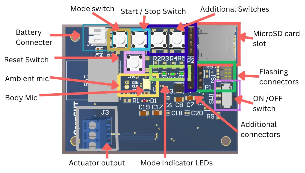
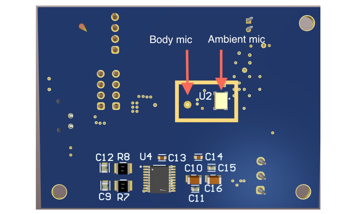
Dual digital microphones:
A body-facing microphone captures abdominal acoustic signals, while an ambient-facing microphone records environmental noise. The two channels are sampled synchronously to support noise-aware processing. We use CMM-4030DB-26354-TR PDM MEMS microphone from Same Sky. Different versions of the OpenGut hardware may have different PDM microphones with similar frequency response, due to availability at time of manufacture.
Microcontroller (nRF52840):
This handles audio acquisition, buffering, and system control. The microcontroller interfaces directly with the dual microphones using a digital audio protocol and manages data transfer to storage. We use the BT840F, the SoC packaging of nRF52840, provided by FANSTEL. This allows easy integration of the MCU onto the chip with BLE antenna integration.
Local storage (microSD card):
All recorded data is written to removable storage, enabling long-duration recording without requiring a continuous wireless connection.
Power system (LiPo battery):
The device is battery-powered for wearable use, supporting extended recording sessions depending on configuration. The battery is connected using a JST connection. This allows researchers to use batteries of their preference which allows for compromise between capacity, size, and weight. We use a 1000mAh battery because it allows 24 hours of continuous recording.
Actuator interfaces (optional):
External connectors allow integration of output devices such as headphones (audio) or haptic exciters for playback and feedback. We have integrated a DAC output channel. Researchers can connect external amplifiers as they wish to play back either haptic feedback or real-time visualization using a headphone-amplifier.
Acoustic interface and enclosure:
A diaphragm-based interface and 3D-printed acoustic coupling structure improve transmission of body-borne sounds to the microphone. The system is housed in a compact enclosure and worn using a stretchable belt.
Firmware and Data Flow
The firmware is developed using the nRF connect SDK on VS code. We have modularized the code in such a way that anyone can easily make changes to specific subsystems. The embedded firmware manages synchronized data acquisition, configuration handling, and system operation modes.
At runtime, the system follows this data flow:
-
All four indicator leds blink once, followed by
LED 1being turned on continuously. -
User can select the mode by pressing the mode selection switch.
- Short press - next mode
- Long press - previous mode
- Four modes are possible, which are indicated by each of the four LEDs.
- Mode 1: Stereo recording
- Mode 2: Real time playback
- Mode 3: Playback of file A
- Mode 4: Playback of file B
-
Once mode is selected, press start/stop button.
-
In mode 1 (stereo recording), both microphones continuously capture audio. This uses the left/right channel differentiator and stores data using ring buffers.
-
The buffered data is written to the SD card in blocks of 100ms.
-
Once the stop switch is pressed, the led blinks 3 times before concluding the operation.
-
While a mode is operating the led associated with it blinks continuously. Each mode has a designated led that blinks.
-
In mode 2, the captured stereo audio is redirected using I2S to the DAC. This output can be connected via the 3pin JST which allows realtime loopback, visualization or haptic feedback.
-
In modes 3 and 4, the respective audio file is played via the output.
This architecture of this system allows it to operate independently of a host computer during data collection.
Software Interface
A desktop graphical user interface (GUI) provides tools for hardware configuration, audio sample visualization, audio processing (filtering), and audio annotation.
The interface supports:
Hardware configuration
Users can define hardware operation mode (logging, playback, loopback), and parameters for audio recording and playback. The configuration will be exported in JSON format which can be loaded to the hardware through microSD.
Audio visualization and playback
An acquired audio file (wave format) can be presented in waveform and/or spectrogram visually, as well as simple playback control to listen to the data, so that users can observe the signal and analyse it.
Audio filtering
Prior to further data assessment, users can apply a high-pass filter (implemented with SciPy) or a machine learning algorithm-based filter (AudioSep). Users can specify expected output by natural language (i.e. “Gut sound without any other ambient noise or sound”).
Audio annotation
Users can annotate any segment of audio timeline, by selecting a segment and attaching a unique title, description, and color tag.
Post-annotation data export
Users can export the segments of audio with annotated metadata as subdivided audio files. This feature assists users in collecting data samples and prepares the data for operations such as machine learning model training or other applications.
The software operates offline and interacts with the hardware through file-based workflows (via the microSD card).
System-Level Operation
Together, these components support three primary modes of operation:
- Logging mode: continuous acquisition and storage of gut signals
- Playback mode: rendering of recorded signals through output devices
- Real-time loopback mode: immediate feedback from live input signals
These modes are configured through the software interface and executed by the embedded system without requiring continuous external connectivity.